

 Thanks: 2
 Likes: 22
 Needs Pictures: 0
 Picture(s) thanks: 0
Results 1 to 15 of 43
-
30th March 2013, 11:11 PM #1
 .
.


- Join Date
- Feb 2006
- Location
- Perth
- Posts
- 24,746
 Building a natural gas forge - WIP
After making a few enquiries, discussions with the electrical furnace lads where I used to work, some calls to furnace suppliers, a few late nights on the internet and a few PMs with Corin I have decided to have a crack at building a natural gas fired forge.
The requirements are
- it has to be mobile as the only natural gas point we have outside the house is on the back veranda. SWMBO says I can use it there but when guests come it has to be removed at very short notice. Also a couple of other members have expressed interest in using it.
- Has to be able to anneal, harden and temper wood work tool blades up to ~10" long - it would be nice to be able to be able to go longer but that is not high on the priority at this stage
- Initially it has to be natural gas powered,
- has to be quick - can't afford to hand around waiting for heat up (OTOH that means it cannot be left unattended so lengthy heat treatments are unlikely)
So this is where I am currently at
Yes I agree it looks like something homeland security might be knocking on my door about soon.
The trolley is all ally jobbie I fished out of the skip where I used to work. It used to support a large 1960's Storage CRO that stopped working and was thrown out years ago.
The trolley has solid lockable wheels and a drawer a nice handle to move the whole thing around even when it is hot. The handle can also be used to hook forge tools over.
The forge body is supported on steel legs 110 mm away from the trolley to improve working height and also to protect the trolley.
The space underneath will be used to locate a small blower. Because natural gas does not have much energy and is also delivered at low pressure the high temperatures needed in forges can only be obtained using force/blown torches - more about that later.
Most of the 3/4" galv plumbing pieces and pipe come from my FILs bottomless box of plumbing pieces. The 1/2" stuff comes mainly from leftovers after installing the retic compressed air in the shed. So far I guess I have spent $40 on taps and bits and pieces.
The body of the forge is based on a small LPG bottle but what I have been focussing on mainly so far is the gas and air plumbing components.
There is still a fair bit of work to do on the body like cutting the ends off and cutting doorways at either end and adding small doors and then of course lining the interior etc
AFter lining and adding a refractory brick floor there will be ~8" of working diameter and an internal working length of ~14" which I am pretty happy about.
I am also making the entire ends of the bottle into large doors on hinges so that they can be opened up to view the torch tip positions more easily, and so the lining can be more easily replaced when required.
Because the interior of the forge after lining will be ~700 cu in the recommendation is to use two torches for that volume.
Here is one of the torches
The nozzle is 304L stainless to cope with the high temperature at the torch tip.
I can get a nice blue cone from this torch but for better flame stability the tip is supposed to be flared - something else to have a look at.
The T-piece with the wire coming away from it is a BBQ lighter point.
The chrome tap and all the flexy gas lines come from a skip outside a lab reno where I used to work and they are proper lab gas taps and hoses.
The big steel collar on the porch locks the torch to the tank and enables the height of the torch in the tank to be adjusted via a couple of grub screws
This is what the operator will see in front of them
The yellow handle lever tap is the master gas switch.
The two taps with the yellow tops are gas flow control to each torch
The red handles on the left (yes there are two - one is behind the topmost gas tap) are air flow control to each torch.
The blue handle and red handled taps on the right are part of an idle circuit - more about that later.
Here you can better see the master gas control (yellow lever) and the idler circuit (blue and red handled taps)
Here is a view from the other side showing the two air controls (red handled taps)
The large 25 mm brass adapters at the very top are forced air input lines - they don't have to be that big and I will probably scale then down when I sort the blower out.
Here is a view of the torch tips inside the tank,
Bear in mind 2" of insulation need to go around the inside of the tank - the torch tips should not be protruding below the lining..
You can also see how rusty the inside of the tank was.
The black gunk is the effect of phosphoric acid on the 1/2 mm thick layer of rust.
Nothing has been finally bolted or sealed in place. The bolts protruding into the tank will be turned around so that only their heads are inside the tank so they don; interfere with the lining.
In terms of a forced air supply I have been experimenting with a vacuum cleaner that has variable speed air flow control but even that seems to be way too much air so I had to add air flow control taps and spill most of the air during the testing with one torch - I don't expect much will change with two torches. I picked up a nice gentle blower out of a blower heater yesterday during kerbside pickup that might work - have to take a look at that more closely. Anyway -I have done enough experimentation to feel confident enough that it should work so I am working on the furnace body and plumbing first.
The build is a slow process (much slower than I thought it would be) but I am enjoying it and can't wait to make some heat.
-
31st March 2013, 12:19 PM #2
Senior Member
- Join Date
- Dec 2009
- Location
- Sydney
- Posts
- 249
Flash stuff Bob!
I can't wait to hear how the firing goes; looks like you'll be able to forge out of it as well as heat treat.
Tried a vacuum cleaner as a blower, just rather noisy, and as you pointed out, more than enough air. On the 6" out let blower at the Heritage Fleet I made a manifold with spigots to tap off air for heat treating (eg air hardening), extra forges and air curtains.
enjoy,
AndrewOC'Waratah' spring hammer by Hands & Scott c.1911- 20, 'Duffy, Todd & Williams' spring hammer c.1920, Premo lathe- 1953, Premo filing machine.
-
31st March 2013, 02:42 PM #3
GOLD MEMBER
- Join Date
- Dec 2010
- Location
- Mornington Peninsula
- Posts
- 2,464
Looking good. Consider getting a variable pressure regulator for the supply gas bottle as it will give you more control and a safety margin.
Consider this regulator.
LPG Regulator
-
31st March 2013, 03:19 PM #4
.
- Join Date
- Feb 2006
- Location
- Perth
- Posts
- 24,746
Cheers Andrew, yeah funny how I started out by considering a 9kg gas cylinder and now I'm heading into two burner territory. Originally Posted by AndrewOC

The vacuum cleaner I'm using (a council kerbside pick up jobbie) is not too bad for noise and has variable speed air flow ranging from 16 to 40 cfm (it sure is nice to have air flow measuring gear on hand to do this) but even the slowest flow is way too much. I like your idea of a manifold and air curtain, what do you use the air curtain for?Tried a vacuum cleaner as a blower, just rather noisy, and as you pointed out, more than enough air. On the 6" out let blower at the Heritage Fleet I made a manifold with spigots to tap off air for heat treating (eg air hardening), extra forges and air curtains.
Originally Posted by cava
Thanks for the suggestion but I'm not using LPG, I'm using natural gas ie the external gas bayonet where I hook up my BBQ. The lab gas taps provide excellent control as they have many turns.
The pressure in at the bayonet is very low (<1 psi) and there is a regulator in the flexy line connecting the bayonet to the forge - pressure after the regulator is also <1psi. I hope this is enough, hence also the need for a blower.
-
31st March 2013, 04:12 PM #5
GOLD MEMBER
- Join Date
- Jun 2008
- Location
- Victoria, Australia
- Age
- 74
- Posts
- 6,057
Hi Bob,
Here is a quieter alternative to vacuum cleaners..
After trying a number of blowers, I eventually settled on a spa blower, extremely quiet and nice and compact.
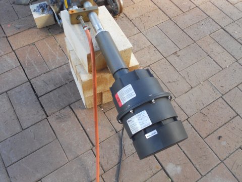
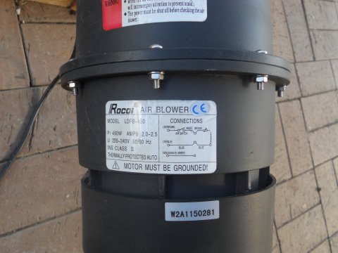
Speed is adjusted with a variac. the model is LDFB 450 I notice that it comes in several brands, but the model number seems to persist across the brands
Regards
Ray
-
31st March 2013, 04:25 PM #6
GOLD MEMBER
- Join Date
- Dec 2010
- Location
- Mornington Peninsula
- Posts
- 2,464
NG has circa 38-40 mJ/m3 and you will need a reasonable sized injector to get the heat you want. <1psi is very low. Don't you mean kPa? Originally Posted by BobL
-
31st March 2013, 11:04 PM #7
.
- Join Date
- Feb 2006
- Location
- Perth
- Posts
- 24,746
Im not using any injector - I'm just running the natural gas pipe direct into the torch with flow control via the gas tap which has a 6 mm outlet. The flame control is basically done by controlling the forced air flow. Originally Posted by cava
1 PSI = ~7 kpa so 1 kpa = .15 psi
I've just got myself a more sensitive pressure measuring device so I can measure the pressure more accurately - I'll do that tomorrow.
-
31st March 2013, 11:11 PM #8
Senior Member
- Join Date
- Dec 2009
- Location
- Sydney
- Posts
- 249
Ahh that be secret blacksmith business! Originally Posted by BobL
Only joking!!
An air curtain can go around the furnace opening, it tends to keep the heat inside the furnace. This helps get your hands closer to the opening or (more importantly) slow down heat creep along a job that is half in the furnace and half outside, where you usually want a cool handle.
Mind you it probably would work best on a furnace with a chimney/ exhaust outlet.
A.'Waratah' spring hammer by Hands & Scott c.1911- 20, 'Duffy, Todd & Williams' spring hammer c.1920, Premo lathe- 1953, Premo filing machine.
-
31st March 2013, 11:38 PM #9
.
- Join Date
- Feb 2006
- Location
- Perth
- Posts
- 24,746
Cheers Ray. Thanks for the lead. Originally Posted by RayG
At this stage the noise from the variable speed VC on it's slowest speed does not seem too bad but I'm usually all for minimal noise.
I do have a whisper quiet blower from a fan heater that is possibly too weak.
I may stick with the VC as I an also a fan of air curtains .
.
-
31st March 2013, 11:42 PM #10
GOLD MEMBER
- Join Date
- Dec 2010
- Location
- Mornington Peninsula
- Posts
- 2,464
Woops. Sorry. I got the psi vs kPa back to front. Originally Posted by BobL

-
14th April 2013, 11:25 PM #11
.
- Join Date
- Feb 2006
- Location
- Perth
- Posts
- 24,746
I did a bit more on the forge in the last few days. I threw a coat of pot belly black on all the external bits to keep the lid on rust as much as I can.
I also installed the insulation/lining this morning - I realize this will be old hat for gas forge gurus but thought some of the woodworkers might be interested in the process if they wandered into this forum.
Cutting up the insulation (I followed Corin's video on the process).
I wore my Triton full face respirator while handling the insulation.
Here you can see the main body and two ends ready to go back together.
The ends are on large removable pin hinges so it can all come apart for relining when required.
Here it is all back together with the 1" thick silica brick floor. The blue colour is the liquid rigidizer which is sprayed onto the exposed fibre to stop it being damaged and fraying and then blowing around with the exhaust gasses
There is a firebrick door that covers the 8" wide opening - more pics tomorrow
Now I have to wait for the rigidizer to dry - reassemble the torches and everything else and do a firing to fully set the rigidizer.
Cheers
Bob
-
15th April 2013, 04:39 PM #12
.
- Join Date
- Feb 2006
- Location
- Perth
- Posts
- 24,746
First firing
This morning I managed to find the last few bits and pieces and the rigidizer had dried so I was able to fire it up.
Here it is finally all together.
The air supply currently comes from an 1800 W vacuum cleaner but I am still exploring quieter options.
The VC has variable air speed control and at the slow speed it draws about 3A (1HP).
The VC outlet has been covered over with a 50 mm sewage pipe and then it splits two ways
Most of the air is directed to AndrewOC's idea for an air curtain .
The air curtain exits from a frame in front of the door - the frame can also hold a piece of heat proof glass from an old kitchen oven so that the interior of the forge can be viewed without frying yourself.
Here is a close up of the door. the counterweight is a 3kg cast lead ingot which balances the 1" thick silica brick and steel door via a SS cable - it works really well and sits wherever it is put.
If the door is left open the lead ingot gets warm but I could still move it with my bare hand.
I haven't optimized anything (can't see the flame too well in the daytime) but after 5 minutes a 1/2" steel bar seems to be glowing quite nicely.
Here is a view from the back showing the pass through opening for handling long objects.
It also acts as an exhaust vent.
I was only using the front torch but even after 15 minutes I could still touch the back of the forge shell without any problem - the front was hotter but nowhere near as hot as pot belly stove.
-
15th April 2013, 06:49 PM #13
.
- Join Date
- Feb 2006
- Location
- Perth
- Posts
- 24,746
Now with two torches running
After a bit of mucking about I managed to get the second torch to fire up. It turns out the easiest way to do this is just to open up the gas and air taps to the max with the vacuum cleaner on slowest speed, and then crank up the revs on the VC to about 1/3 of max.
The two bright spots at the top signify the two torches are alight.
twotorches1.jpg
After a couple of minutes the two hot spots from the two torches clearly show up on the floor of the forge
twotorches2.jpg
The two torches generate about 10" of working length on a piece of metal - i'm pretty happy with that.
RHP.jpg
Once the forge is fully warmed and running (about 10 minutes) it takes 2 minutes to heat up a 12 mm rod to working temp.
Running cost is about $2.80 an hour.
-
15th April 2013, 07:48 PM #14
.
- Join Date
- Feb 2006
- Location
- Perth
- Posts
- 24,746
I remembered I had a Thermocouple rated for 1600ºC in my shed and have spent half an hour turning the shed upside down and manage to find it. I then cranked the forge up again and got it to 1189ºC before it seemed to top out. I have not played around with the air/gas mix much (I just have them fully open with the VC on 1/3 of max revs) so maybe I can get some more out of it.
I'll let it cool down overnight and do a temp/time graph for a heat up tomorrow morning.
-
15th April 2013, 08:28 PM #15
Lignum Vexator
- Join Date
- May 2007
- Location
- North of the coathanger, Sydney
- Age
- 68
- Posts
- 0
Interesting
can you do me a couple of horse shoes?
regards
Nick
veni, vidi, tornavi
Without wood it's just ...


