

 Thanks: 0
 Likes: 0
 Needs Pictures: 0
 Picture(s) thanks: 0
Results 1 to 15 of 17
-
2nd October 2007, 11:53 PM #1
 New Member


- Join Date
- Sep 2007
- Location
- adelaide
- Posts
- 6
- Post Thanks / Like

 Cathedral Ceiling Pergola - Comments.
Hello,
I live just out of Adelaide in Marleston 5033, I believe its a standard wind rated area.
I'm in the designing stages of a new pergola to replace my existing one. I have attached a couple of images from Google SketchUp of the new pergola I have designed. Last week I spoke to a council building engineer about my design so far and he gave me some good feedback and confirmation about fixing methods to be used for the footings, rafter brackets, rafter to ridge connections etc ...
The timber I have selected to use is Futurebuilds HySpan LVL product. This is because of the large structural ridge beam i wanted for my cathedral ceiling look. All my beam loads were calculated with the software 'designIT' from http://www.timberbuilt.com.au/softwa...nit/index.html .
The size of my pergola is 10m x 5.5m x 3.2m, it will be attached to the existing rafters of our 1928 bungalow using steel rafter brackets. The roof will be 2/3 colourbond and 1/3 suntuff solar control. The following is the timber sizes(mm) I have selected to use:
Ridge Beam - 1 @ 525x75x10m, Single span supported by rafters and end supports
Front/Back Beams - 2 @ 300x45x5.5m, Single span between post and house
Road Side Beam - 1 @ 300x45x10m, Continuous span supported by 3 posts
House Side Beam - 1 @ 240x36x10m, Continuous span attached to 8 metal rafter brackets
Rafters - 22 @ 200x36x2.7m, 9 main rafters each side spaced at 1245 centers
Purlins - 70x35, Secured using batten screws
Posts - 3 @ 150x150x3.2m, Cypruss Pine, footings 300x700 using pryda high wind post anchors (150x600).
All supporting LVL beams facing the weather will be H3 treated and all LVL will be undercoated and painted.
After speaking to the council building engineer he made the following suggestions. Use a strongarm (90x45x1800) on the opposite side of each rafter to which each metal rafter bracket was to be attached, nail metal strapping over each existing house rafter. He was happy with the fixing methods I had planned for attaching the rafters to the ridge beam, this was using pryda minigrips on each side of every rafter, skew nailing each rafter and nailing a strap over to the opposite rafter. Using pryda joist hangers (180x40) to brace the rafters to the side beams. All bolts, nails etc are to be galv.
I have a question regarding the 'rafter to ridge' and 'rafter to beam' connections:
Would I be able to do without the pryda minigrips and joist hangers if i route out a 5-10mm space for the rafters to sit in and skew nail them in only (still using strapping for the top connection), I would prefer the look of this compared to the pryda connections?
What I wanted was a chunky look and wood gave me this (I dont mind the steel pergolas from Stratco etc) and reason I originally went with LVL was that I wanted a 'cathedral ceiling' with a clean look - no collar/rafter ties, this seemed to be the only solution in timber for the 10m span.
Would it be possible to use hardwood for this design and also keep the costs similar to the price of LVL?
Any comments welcome.
Thanks,
Nic Harding
-
4th October 2007, 02:05 AM #2
Success varies
- Join Date
- Sep 2007
- Location
- Sydney
- Age
- 63
- Posts
- 133
- Post Thanks / Like
Nic, some of those timbers sound HUGE, have you thought about doing it in steel?
I just finished a pergola that is a bit wider at the widest and as long as youre but all done in steel RHS. My ridge beams are 150X50X3, rafters 100X50X3 and posts are 89X89X3.5. My design but all the members checked by an engineer. It is soon to be inspected by the certifier but it stood up to all the wind and rain we had a few months ago.
The posts are to be built into the walls of the existing garage and adjacent house extension which is in progress.
I would post some pics but I couldn't last time I tried.
Alan M
-
4th October 2007, 05:26 AM #3
Wood - Hunter/Gatherer
- Join Date
- Jul 2005
- Location
- Brisbane
- Age
- 65
- Posts
- 25
- Post Thanks / Like
The spans are big, the timbers are big.
Have you considered whether the existing roof can take this sorta load at the tips of the eaves. I have just added a 7 x 7m awning to my roof and to attach it similar to yours I put 75 x 75 steel angle to the top chord of the existing trusses to allow the load on the end of the eaves.
I don't see any bracing in the log direction either - you have something in mind?
Although this roof may hold it'self up have you also taken into account it holding it'self down - you may need additional rods into the footings at the connection to the existing roof - this is a big parachute don't forget.
Check with your council that you can get away without having an engineer design and certify this - it seems big compared to most awnings in the spans you are having 10m ridge span then bearing mid-span onto a 5.5m span each end will create large loads locally and must be carried down to the footings -similarly must be anchored down so it does take off and take your house roof with it.
This project is more than sizing timbers.
Good luck.Cheers
TEEJAY
There is a very fine line between "hobby" and "mental illness"
(Man was born to hunt and kill)
-
4th October 2007, 07:30 AM #4
SENIOR MEMBER
- Join Date
- Apr 2005
- Location
- Sydney
- Age
- 65
- Posts
- 882
- Post Thanks / Like
As TEEJAY says, that span is 10metres and I'd be surprised if the council just lets it go. You can't count on the rafters carrying the beam. If it wants to go down it will push out the central post.
According to the LVL tables on their site, you need at least 2/300x45s, or 1/300x63 on each end (not considering the point load), and I don't think he'll like the way they're notched out for the gutter on that drawing.
The tables don't go up to a 500x75 but ten metre lengths will probably have to come on a semi. I'd just put another beam in the guts, and two smaller ridges, then you might get away with it with a bit of speedbrace thrown in.
But unless that program spits out certifications for everything, I reckon the council will want you to get an engineer, especially if you want to notch the beam for the rafters.
-
4th October 2007, 02:30 PM #5
Senior Member
- Join Date
- Feb 2006
- Location
- vic
- Posts
- 174
- Post Thanks / Like
I would imagine if you bolted collar ties on every second rafter you would get away with a smaller ridge, as its no longer loadbearing, you could join this with fishplates. Rafter ridge connection could be hoop iron strap from rafter to rafter over top of ridge, side beam/ rafter connection they may accept a couple of 150mm bugle batten screws if you dont like the look of joist hangers. Have you thought about contacting a truss company to do a truss with a bottom chord 2/3 the way up the truss, does it have to be cathedral.
-
4th October 2007, 03:15 PM #6
New Member
- Join Date
- Sep 2007
- Location
- adelaide
- Posts
- 6
- Post Thanks / Like
Im not against steel but I prefer the look of timber, a solid bulky look. That doest mean I would not choose steel in the end though, we have had a quote from a company here in SA that deals with Fielders and they quoted a DIY kit for $8200, it comes with most everything except concrete for the footings.
The house in question is a 1928 bungalow with double brick walls. The rafters are spaced at approx 1290mm, as it is an older house there is no truss work like the newer houses - just looks to be very minimal compared to them (in my own opinion).
Alan M,
- How much did your steel structure cost in the end? Was it from Stratco etc.. or sourced yourself from elsewhere?
TEEJAY,
- I like your idea of the 75x75 running up the length of each rafter.
- What did you mean by " I don't see any bracing in the log direction either..."?
- When you said "...you may need additional rods into the footings at the connection to the existing roof". I take it you mean the house footings under the wall, if so that would be a very long rod from eave to footing (4m or so).
- After talking to the council building inspector today he pointed out i used the wrong Roof Load Width for the Front & Back Beams which support the Ridge Beam. He said I should of used half the distance of the ridge as thats the load it was carrying, so I put that into designIT3 and now have a beam of size 400x63x6m. My total width now is 6m, from the brick wall to the post edge. Look at the new attached image for notch out under gutter and sizes.
- What are your thoughts on the point load where the ridge beam attaches to the 6m supporting beams underneath (look at attached image for detail). I have detailed a 90x90 post atched to the ridge beam at the top by steel brackets and bolted through the 400x63 beam and 90x90 post by M12 galv bolts.
Q. Any suggestions for a better/diffrent approach than using a 90x90 post to support the ridge? Maybe a 45degree support instead or as well?- As for the load on the 400x63x6m beams at each end of the ridge I phoned Timberbuilt technical support about using a large 525x75x10m (252kg) ridge and they said the load calculations have been designed even for this size ridge inc. rafter and sheet roof.
- Your right the pdf tables don't go to 575x75 you have to download the designITv3 software, this has all the latest span tables, you can download the latest updates through here as well.
Thanks,
Nic Harding
-
4th October 2007, 03:42 PM #7
New Member
- Join Date
- Sep 2007
- Location
- adelaide
- Posts
- 6
- Post Thanks / Like
thebuildingsurv,
My original thoughts at the time were that a cathedral look was very clean and neat with an open airy feel not constrained by a low rafter/collar tie.
When you explained about using collar ties every second rafter I'm open to the idea.
Q. Is there a resource that you can point me to which tells me what size timbers i need depending whether I need a collar tie every rafter of every second or third etc.. this would be handy because all I had to use was the software for LVL and this has not got any collar tie calculations built in?
I also like the idea of no joist hangers.
Sourcing a truss also is good advice and a time saver. How does the truss fit to the ridge, does it have a notch cut out at the top?
-
4th October 2007, 04:05 PM #8
Senior Member
- Join Date
- Feb 2006
- Location
- vic
- Posts
- 174
- Post Thanks / Like
with truss there is no ridge. I'd go the collar ties every second rafter, its kind of an unwritten law of building surveyors, there used to be a book called "carports and pergolas design and construction manual" put out by the timber promotion council, dont know if its still around. Bring your sketch to the local shire and ask him if this is sufficient method. Its generally accepted here in vic for pergolas up to about 6m in width. The collar ties prevent the rafters from spreading which assist in holding up the ridge, you cant put them up to high though suggest the lower third.
-
4th October 2007, 06:26 PM #9
SENIOR MEMBER
- Join Date
- Feb 2003
- Location
- Garvoc VIC AUSTRALIA
- Posts
- 3,208
- Post Thanks / Like
As the rafters are 1245 spacings you would need collar ties on every pair of rafters.
-
4th October 2007, 09:49 PM #10
Wood - Hunter/Gatherer
- Join Date
- Jul 2005
- Location
- Brisbane
- Age
- 65
- Posts
- 25
- Post Thanks / Like
Nic,
I mean't bracing in the LONG direction - that is what do you have in mind? You can do nothing and it will at least wobble or worse collapse or you can brace the frame by
Knee brace posts to edgebeam or
Diagonal brace between posts or
Diagonal brace roof under roof sheeting with strap of steel or timber notched into rafters
The strengthening of your existing truss top chord must extend a distance beyond the point it sits upon your house wall. If the top chord is going to fail (in bending) it will do so at the place it sits upon the wall - location of maximum bending moment. I went for overkill on my roof with eaves 450 and angle steel 3m long bolted to top chord at point above wall support and at end of angle up in the roof - it ain't going no where. One day a cyclone will reach Brissy and when it does this parachute isn't taking my roof off.
How are you fixing your timber posts to ground? Metal stirrups into concrete pads are durable but are also a "pin support" offer no bracing to your awning in framing action - hence you need bracing.
And yes Nic if you need more holding down for your roof you will need to take it down to something substantial - here we use threaded rods in the wall cavity and epoxy them into the concrete footing and they go up to roof truss and are strapped over this - you have a very big kite there so are you holding it down properly?Cheers
TEEJAY
There is a very fine line between "hobby" and "mental illness"
(Man was born to hunt and kill)
-
5th October 2007, 01:19 AM #11
Success varies
- Join Date
- Sep 2007
- Location
- Sydney
- Age
- 63
- Posts
- 133
- Post Thanks / Like
Hi Nic,
The design is all mine, it is a large open gable structure with a smaller gable attached. The engineers only amended the sizes of a couple of the members from what I proposed initially. It does have a couple of collar ties but they are very high up so they don't close it up at all.
The steel came in 8 mtr lengths and came from Orrcon. The roofing, flashings and gutters came from Stratco.
All up costs including engineering was under $5000, but you must think that my wife and I did all the fabrication work and erection. I even made a crane to lift the heavier pieces into place.
I did get a qoute from stratco for supply only and was shocked to see a figure of over $19 grand delivered (if I remember right that was with insulated roofing though).
I am fussy but I am really happy with the result.
Alan M
-
5th October 2007, 10:32 PM #12
Wood - Hunter/Gatherer
- Join Date
- Jul 2005
- Location
- Brisbane
- Age
- 65
- Posts
- 25
- Post Thanks / Like
Was this supposed to come with pics Alan? Originally Posted by Make it work

Nic,
Here is the awning I connected into my roof
https://www.woodworkforums.com/showthread.php?t=52781
- it cost me about $4000 and yes I did build it myself. It is connected to tips of existing roof trusses of house and therefore has only one column to ground. I went for steel frame and then line it with timber.
Roof weighs 1 tonne - will add another 1 tonne of timber cathedral ceiling yet.Cheers
TEEJAY
There is a very fine line between "hobby" and "mental illness"
(Man was born to hunt and kill)
-
6th October 2007, 02:15 AM #13
Success varies
- Join Date
- Sep 2007
- Location
- Sydney
- Age
- 63
- Posts
- 133
- Post Thanks / Like
I worked out where I was going wrong with posting pics.
Pop up stopper settings...
Here goes, this is my home made awning...
The last one is of my home made crane at work.
One day I will add some fretwork but for now I am flat out building the house extension.
Cheers
Alan M
-
6th October 2007, 08:56 AM #14
Wood - Hunter/Gatherer
- Join Date
- Jul 2005
- Location
- Brisbane
- Age
- 65
- Posts
- 25
- Post Thanks / Like
Awesome lifting device Alan Originally Posted by Make it work

Here you'll see how I managed to lift my 350kg middle roof portion of steel and timber into place
https://www.woodworkforums.com/showthread.php?t=21713
I guess woodworkers are pretty good at improvising.Cheers
TEEJAY
There is a very fine line between "hobby" and "mental illness"
(Man was born to hunt and kill)
-
6th October 2007, 11:03 AM #15
SENIOR MEMBER
- Join Date
- Apr 2005
- Location
- Sydney
- Age
- 65
- Posts
- 882
- Post Thanks / Like
I'm sure that a 90x90 would be alright, but when there are point loads going on a beam the load calculations are different to just applying an even load as worked out in tables. All the load is going on the centre of the beam which is its weakest point, and it generally requires an engineers calculations. I'm a builder, not an engineer, but in my studies they taught us how to do those calculations. Originally Posted by niczoom
There would be a bit of uplift there and top plates should always be strapped down, at least with hoop iron extended down the brickwork. It depends on the wind category, and engineers assessments. Originally Posted by niczoom
You seem to be relying on the existing eaves overhang to carry the new internal beam, and part of the new roof, so I'd say that those stiffening plates should extend up the rafters some distance as well, so they cantilever. If they stop at the top plate then they'll serve no use at all. With enough load, the existing rafters will break at the top plate, with or without the stiffeners.
The cut out for the gutter may be alright since towards the ends the beam is more in shear than in tension/compression, but again, I'm not an engineer and I can't certify anything. As I said, I'd be surprised if the council certified anything that was more than a straightforward interpretation of Australian Standard span tables, but I suppose you never know.
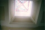
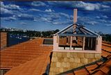
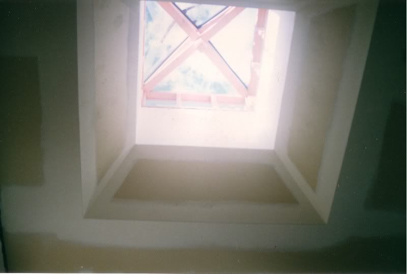
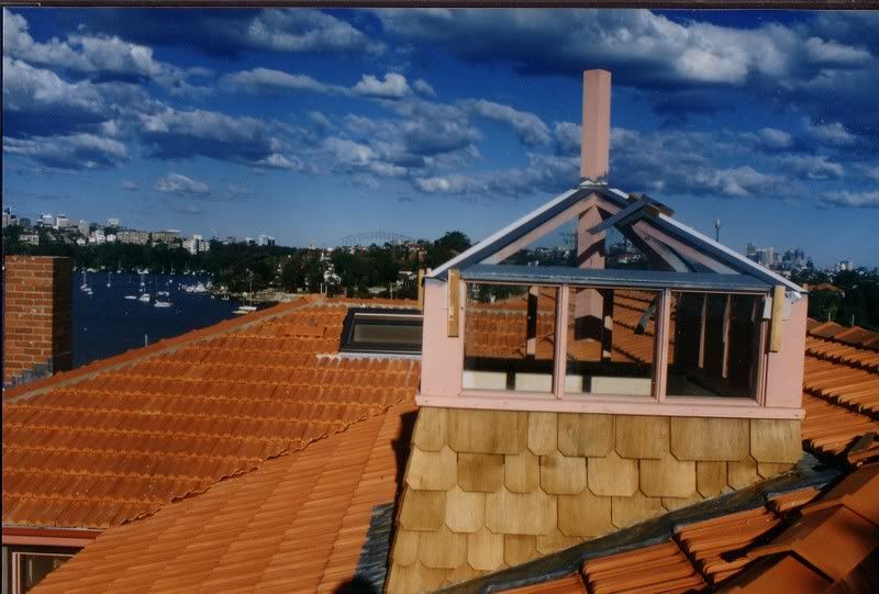
Nice looking awnings you've built there Alan & TEEJAY. I like the cedar 'lighthouse' on top. I built something similar in timber myself a while ago. It had a glazed roof and windows, and a weather vane was installed on

 Reply With Quote


Similar Threads
-
Repairing sagging ceiling plaster at edge of brick wall
By tryhard67 in forum PLASTERINGReplies: 9Last Post: 7th July 2007, 07:16 PM -
Wall to Cathedral ceiling plaster
By OBBob in forum PLASTERINGReplies: 5Last Post: 25th January 2007, 02:30 PM
Bookmarks