

 Thanks: 0
 Likes: 0
 Needs Pictures: 0
 Picture(s) thanks: 0
Results 61 to 75 of 90
Thread: Lubrication System
-
28th June 2012, 10:29 PM #61
 Blacksmith, Cabinetmaker, Machinist, Messmaker


- Join Date
- Dec 2011
- Location
- Canberra
- Age
- 40
- Posts
- 4,432

These look interesting.....i'm sure you could make something similar......
Needle Pinch Valve - Flow-rite Controls | eBay1915 17"x50" LeBlond heavy duty Lathe, 24" Queen city shaper, 1970's G Vernier FV.3.TO Universal Mill, 1958 Blohm HFS 6 surface grinder, 1942 Rivett 715 Lathe, 14"x40" Antrac Lathe, Startrite H225 Bandsaw, 1949 Hercus Camelback Drill press, 1947 Holbrook C10 Lathe.
-
30th June 2012, 07:18 PM #62
Blacksmith, Cabinetmaker, Machinist, Messmaker
- Join Date
- Dec 2011
- Location
- Canberra
- Age
- 40
- Posts
- 4,432
I got my main distribution manifold done today. Its pretty simple, and only 3 way, one for each axis, with taps. After Mark (Graziano) asking about knobs i thought i would just construct the manifold out of parts and cast the whole lot in resin. I just used clear and cast it in the bottom of a 3l milk carton with a tight hole drilled for each pipe. I'll pull it out tomorrow and see how it went.
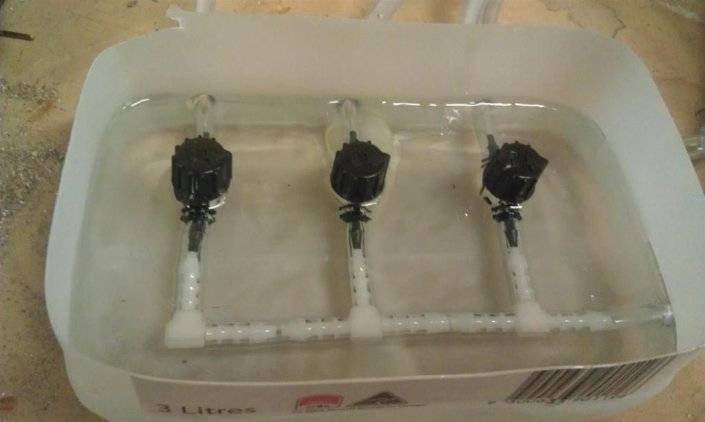 1915 17"x50" LeBlond heavy duty Lathe, 24" Queen city shaper, 1970's G Vernier FV.3.TO Universal Mill, 1958 Blohm HFS 6 surface grinder, 1942 Rivett 715 Lathe, 14"x40" Antrac Lathe, Startrite H225 Bandsaw, 1949 Hercus Camelback Drill press, 1947 Holbrook C10 Lathe.
-
30th June 2012, 10:40 PM #63
GOLD MEMBER

- Join Date
- Aug 2011
- Location
- Melbourne
- Posts
- 2,947
Well not much done by me lately. The billy lids and wife came down with the flue so been busy tending to their needs
 . ALso worked overtime last night. Actually in the end I would have worked for free just to get out!
I have decided to run 3 smaller manifolds, one for each axis. Two of the manifolds will now be housed inside the saddle, each side of the X leadscrew. each manifold will lube the corresponding ways and leadscrew. All 3 lines will then go to another manifold and use one of those flow control needle valves. I think this system will be easier to manage and control. The 3 manifolds for each axis will still have restrictions in them but not to control total flow, only to portion the correct flow to the ways and screw.
Hopefully I will get more done soon....
Ewan, the resin manifold looks great. Thats' a great idea!
Simon
-
2nd July 2012, 09:40 PM #64
SENIOR MEMBER
- Join Date
- Apr 2012
- Location
- Healesville
- Posts
- 599
hmmm..... this link from rusel
AquaBid.com - Item # airpumps1341364217 - 12 LOT 3 WAY BRASS AIR CONTROL VALVE NEW! - Ends: Tue Jul 3 2012 - 08:10:17 PM CDT
LOT OF 12 BRASS 3 WAY AIR CONTROL VALVE. NEEDLE VALVE ALLOWS FOR PRECISE .....................................
Currently $1.00 - No reserve
-
3rd July 2012, 10:27 AM #65
GOLD MEMBER
- Join Date
- Jul 2006
- Location
- Adelaide
- Posts
- 2,661
doing a search for stuff for work and came across site who had needle valves...thought you guys might be interested..seem cheap enough for brass
but dont hit me if they're no good
Needle Valves
-
3rd July 2012, 08:59 PM #66
GOLD MEMBER
- Join Date
- Aug 2011
- Location
- Melbourne
- Posts
- 2,947
Thanks shed & Eskimo!
I will probably end up having to use some form of flow control valve in the end. So I will most likely use something like this:Push to connect Fitting Elbow Pneumatic Speed Flow Control 4 mm OD - 1/4" Thread | eBay
They are cheap and seem pretty easy to set and forget.
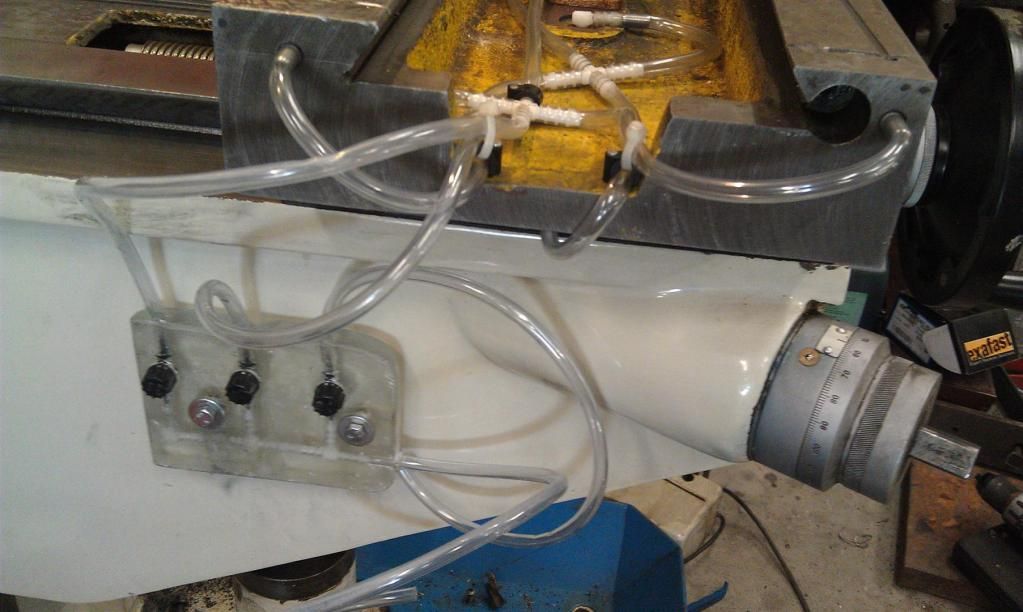
Well I have been out in the shed today and my clear 4mm & 6mm airline tube arrived in the mail. Local supplier only had black. Not too much of an issue but I want to know if I have any air locks in the system.
Like I said earlier, I had gone away from one long manifold and have decided on one for each axis of movement. I will most likely have separate controls to allow individual lubrication of each axis by some form of valve. Maybe another manifold attached to the wall with the 3 valves coming off.
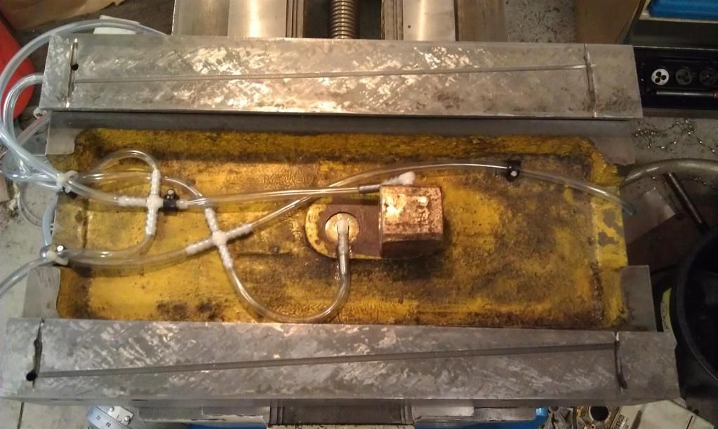
Heres where I'm at so far:
The one stray line is for the X leadscrew. The Y lubricator merely pokes through the saddle and drops oil onto the leadscrew about 20mm away from the nut. Anything more elaborate would require re-routing and some fancier plumbing. If I get into the habit of having the table rearward then it will pick up the lube anyway.
The two manifolds are just sitting there ATM. I haven't decided whether to screw them to the saddle of use a dap of liquid nails
Cheers,
Simon
-
4th July 2012, 02:21 PM #67
Blacksmith, Cabinetmaker, Machinist, Messmaker
- Join Date
- Dec 2011
- Location
- Canberra
- Age
- 40
- Posts
- 4,432
Hi Simon,
That looks really good, i'm glad you not feeling so bad that you can't get into the shed at all. I have also been thinking of how to hold the lines in place, i bought some cable saddles to suit the pipe but the liquid nails idea sounds quick and easy and doesn't mean drilling more holes in the machine.
The link you showed looks like a good idea but the flow control is going the wrong way if you want to use them at the end of the line.1915 17"x50" LeBlond heavy duty Lathe, 24" Queen city shaper, 1970's G Vernier FV.3.TO Universal Mill, 1958 Blohm HFS 6 surface grinder, 1942 Rivett 715 Lathe, 14"x40" Antrac Lathe, Startrite H225 Bandsaw, 1949 Hercus Camelback Drill press, 1947 Holbrook C10 Lathe.
-
4th July 2012, 03:39 PM #68Dave J Guest
Good to see it's coming along. It will save the work of having to individually oiling everything.
Dave
-
4th July 2012, 06:16 PM #69
GOLD MEMBER
- Join Date
- Aug 2011
- Location
- Melbourne
- Posts
- 2,947
Thanks Dave!
Hi Ewan, yes you are correct but if I was going to use them then they would come off the manifold so that the flow direction would still be correct way.
The two existing dilemmas I have are how to "inject" or direct the oil onto the X leadscrew and how to keep the line away from the leadscrew that have to ross under it. In an ideal world I would have plumbed the system so that no oil lines needed to cross over/under the leadscrew but as it turned out there is one that has to.
So, my plan is to create a "bridge" from one manifold to the other and machine a clearance radius for the leadscrew. The OD of my leadscrew is 24mm so a couple of mm clearance in diameter should do. This will allow two things. Give me somewhere to drill, tap and inject another oil line for the X leadscrew and, provide a bridge to attach any oil lines to that need to cross over the leadscrew to the other side of the saddle.
A slightly undersized groove running along this bridge would allow me to push the 4mm oil line into place and hold it there.
Today I made a donut with a flat bottom out of some grey plastic 50mm rod. I was going to place it next to the nut, with the leadscrew passing through it. I was going to use this to oil the leadscrew but there was no room for it one side because of the manifolds and if I put it on the other side it would have obscured the backlash adjustment screw.
It's a work in progress but that where I'm at so far.
Cheers,
Simon
-
4th July 2012, 10:10 PM #70
Blacksmith, Cabinetmaker, Machinist, Messmaker
- Join Date
- Dec 2011
- Location
- Canberra
- Age
- 40
- Posts
- 4,432
Hi,
Got my x and y finished today. It doesn't look nearly as neat as yours Simon but it seems to work just fine. The only leaks to report are where the jets screw into, i think some thread tape or maybe just a spot of RV sealer will fix that. I ended up using the cable clips to hold the tube down, nail and all. The nails were 2mm dia so i drilled some 1.9mm holes and just pressed them in with a clamp. I have left the Y nut with no bolt in it, turns out there is not one there cause the is no space for a head under the x screw Good design that one! The pipe barely fitted and that was after grinding a channel for it into the saddle.
Thread hijack over Simon, i'll retreat to my can o worms now.......1915 17"x50" LeBlond heavy duty Lathe, 24" Queen city shaper, 1970's G Vernier FV.3.TO Universal Mill, 1958 Blohm HFS 6 surface grinder, 1942 Rivett 715 Lathe, 14"x40" Antrac Lathe, Startrite H225 Bandsaw, 1949 Hercus Camelback Drill press, 1947 Holbrook C10 Lathe.
-
4th July 2012, 10:43 PM #71
GOLD MEMBER
- Join Date
- Aug 2011
- Location
- Melbourne
- Posts
- 2,947
That's awsome Ewan.
I like the idea of being able to inject the Y nut through the dowel pin. I wish I had that luxury.
I better pull my finger out and close the deal on my project. It'd dragging on too long.
BTW, hijack away!
Simon
-
4th July 2012, 10:51 PM #72
Philomath in training
- Join Date
- Oct 2011
- Location
- Adelaide
- Age
- 59
- Posts
- 3,148
It's been interesting watching you guys work through this but I've just thought of something which may throw a spanner in the works. Commercial distributed lubrication systems have one way metering valves in the runs so that each branch gets a set amount of oil and then shuts off so that other branches have a chance to get some oil. To use a motoring analogy, with a standard diff on a car the wheel that has least resistance to turning will be the one that spins. Similarly, the branch with the least pressure drop will let the most oil through. I know you have some needle valves in there but will they be sensitive enough to balance the flows? Have you one per branch or one valve for several branches (outlets)?
The original oilers 'worked' because once the oil was in, the oiler sealed and so held pressure. With a plumbed system like this will a weight on the table tend to force the oil back into the pipe?
Michael
-
4th July 2012, 11:01 PM #73
Blacksmith, Cabinetmaker, Machinist, Messmaker
- Join Date
- Dec 2011
- Location
- Canberra
- Age
- 40
- Posts
- 4,432
Its too late to dodge spanners!!! Originally Posted by Michael G

My way of thinking was to use the jets to distribute the flow. The only thing that could happen is the oil could get forced out of the ways and into the lead screws. Also my taps are there to turn off the feed to any axis not being used. At this stage though my 2 ways are getting oil at all 6 points, i couldn't really say if the x is getting more than the y like it was planned, but it looks like the ways are getting more than the nuts. The metering units you mean are 3.50 pound from arc euro so these could be fitted later if the system doesn't seem to be working effectively.1915 17"x50" LeBlond heavy duty Lathe, 24" Queen city shaper, 1970's G Vernier FV.3.TO Universal Mill, 1958 Blohm HFS 6 surface grinder, 1942 Rivett 715 Lathe, 14"x40" Antrac Lathe, Startrite H225 Bandsaw, 1949 Hercus Camelback Drill press, 1947 Holbrook C10 Lathe.
-
4th July 2012, 11:48 PM #74
GOLD MEMBER
- Join Date
- Aug 2011
- Location
- Melbourne
- Posts
- 2,947
Hi Michael,
This issue has been in the back of my mind. In theory if there is the correct amount of restriction in each line that should allow a predetermined flow to each point. The amount of flow to each point from the manifold is a relative figure and the total flow will be decided by how long you decide to pump, hold the button or leave the valve open for. There is room for some fine tuning of the relative flows. As I have (and Ewan) has opted for individual oil lines for each axis, the potential "uncontrolled" flow is only to 3 outlets which means at worse X nut gets as much as the X ways. Y nut gets as much as Y ways and so on. Hardly ideal and certainly not as precise or as elaborate as the arc trade system but it's also a fraction of the cost. As a last resort I will slide wipper snipper line inside the nut lube line to significantly reduce flow.
My main concern is that there most likely won't be as much restriction on the leadscrew nut lines because its not between two flat surfaces but there are means (as outlined above) to address this, hopefully
If all else fails, I'm still getting oil where it's needed which is not something I could say for certain before.
Cheers!
Simon
-
5th July 2012, 12:50 AM #75Dave J Guest
Looks good guys,
 I think you have both done well.
I agree they do have one way valves as Michael said, but the basic commercial system as documented by Bijur, is just jets at specific sizes, where it doesn't have the affects like a diff giving one place oil where needed.
The standard (cheaper) system only supplies oil from the pump to jets which are sized accordingly to each outlet all at the same time, so if one outlet doesn't need it, it's going to get it anyway.
I am talking in the simpler systems here which is the (SLR)
Bijur Delimon Automatic Lubrication Systems : Single Line Resistance
As there is the (PDI) systems as well which are more advanced but you do pay for it as well and would not be easy to copy in the home shop.
Bijur Delimon Automatic Lubrication Systems : Positive Displacement Injector
Most mills have the simpler (SLR) type which is what you have copied, so to split that up into different circuits I think you have a bit of each so to speak.
The way you have done it is more individual than the Bijur standard system, because Bijur just supply it from one spot and rely on the jets to meter the oil to each point.
Ewan,
One way you could have done it is to counter bored for the Y axis nut hole to have a bolt and washer, then drilled/taped the bolt for a oil line which would then have served two purposes. With the Y axis nut being press fit I don't think you will have any problems, but this would have been another way around it to lock the Y axis nut as well.
Dave


