Results 1 to 6 of 6
-
26th March 2008, 11:16 PM #1
 Intermediate Member


- Join Date
- Mar 2008
- Location
- Brisbane
- Posts
- 20
 How Do I Install a Mechanical Gauge (For a Water Tank)?
Alright,
I wanted to ask about this before drilling a nice hole into the top of the tank!.
I have the MT Profil R shown here mechanical gauge. The instructions are very clear on how to calibrate it should your tank be over 1.5m, but what is not clear is how I go about installing it (so it must be simple, but I just don't want to bugger it up ).
).
I have the additional nut fitting (pictured above) which is slightly larger (G2?) than the diameter of the gauge fitting (G 1/2?), the gauge screws inside the nut.
My Qs are :- What is the advantage of using this nut fitting? - just so the level is easier to remove?
- The above link mentions a G 1/2 or G 2 thread, what is that in metric?
- Do I have to use a certain type of hole saw, and what diameter?
- Do I have to thread the inside of the hole once cut, to suit the thread of the nut I an about to fit?
- Can I prevent any plastic off cuts, etc. from falling into the tank - or should I not worry about it?.
- I am thinking of installing it in the green dot indicated below, which is the only other level spot on the top of the tank, any suggestions here?

Any further advice or ideas are appreciated!
Thanks,
Aaron
-
27th March 2008, 04:01 PM #2

eHi Aaron,
I saw these types of gauges being sold on ebay , and almost brought one. Then saw then in Bunnies for half the price of the ebay ones so I jumped on it.
Piece of cake to install. First work out which scale you want to use, turn the face over if required. Depends on the tank height.
Next, throw that threaded ring over your shoulder. If you are going to mount the gauge opposite the inlet mesh basket then you'll need a bloody long arm to reach over to the other side of the tank to screw it on .
.
Get some vernier callipers and measure the thread on the bottom of the gauge and cut a hole a tad smaller than the thread size. Use a hole saw,e or draw a circle with a compass a drill a series of holes and then clean it up with a round file.
Plastic fileings that fall into the tank won't hurt anything, give it a few months and you'll be amazed what's laying on the bottom.
Next just screw the gauge into the tank. The gauge thread is very course and the tank poly is very soft, as you'll find when you drill it.
BTW, the surface that the gauge is mounted to doesn't have to be flat because there is only a nylon cord from the bottom of the gauge to the float. If it's mounted on a slight angle, and the top of the tank is over 2mtrs then it's easier to read because the gauge is
facing slightly forward.
The only problem with these gauges, is they tend to get allot of condensation on the lens.
Have fun.
Turpy.Last edited by Turpy; 27th March 2008 at 04:02 PM. Reason: Typo
-
27th March 2008, 05:17 PM #3
 Intermediate Member


- Join Date
- Mar 2008
- Location
- Brisbane
- Posts
- 20

Thanks Turpy your a legend

Now I guess you mean that the threaded nut was supposed to go on from the inside? - I thought it just went on from the outside!
I didn't want to make hole in the tank and then find it the gauge would fit!, but if the hole is too small I can always use the file as you suggested!.
-
27th March 2008, 09:55 PM #4
-
6th April 2008, 12:32 PM #5
 Intermediate Member


- Join Date
- Mar 2008
- Location
- Brisbane
- Posts
- 20

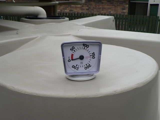
I thought I would post a picture of the finished product, the closest holesaw I had was a 54mm, which matched the nut and was too big for the gauge.
So I used that then had to file it out to make it a little larger. Worked out well in the end.
Here is what it looks like, it faces the kitchen so u can see how much water is in the tank from inside.

-
6th April 2008, 12:34 PM #6
Similar Threads
-
Mechanical subfloor ventilation
By JIT in forum PLUMBING, ELECTRICAL, HEATING, COOLING, etcReplies: 2Last Post: 11th August 2006, 02:33 AM


Bookmarks