

 Thanks: 0
 Likes: 1
 Needs Pictures: 0
 Picture(s) thanks: 0
Results 16 to 26 of 26
-
3rd August 2013, 07:43 AM #16
 Intermediate Member


- Join Date
- Jul 2013
- Location
- Asia
- Posts
- 33

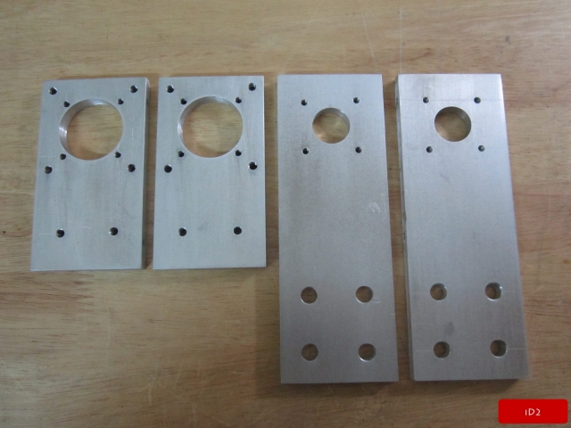
OK, Let working with ball screw mounting plate for X Axis.
More pictures , iD2CNC.wordpress.com
X Axis ball screw mounting plate ::

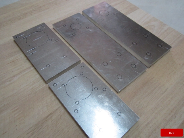

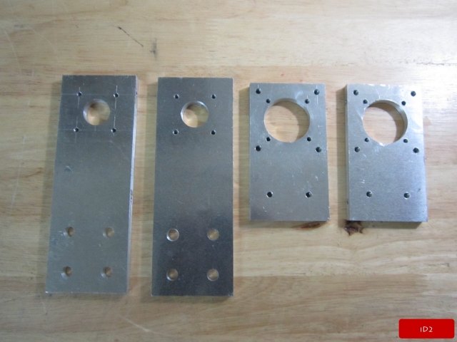
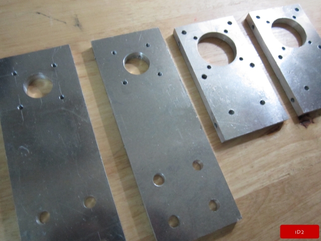
After did abrasive paper ::

-
3rd August 2013, 11:33 AM #17
GOLD MEMBER
- Join Date
- Feb 2004
- Location
- Oxley, Brisbane
- Age
- 79
- Posts
- 1,826
On the pictures of your Z axis, the positioning of the slide blocks behind the spindle mounting plate seems to lose you a fair bit of potential movement.
From what I can see of your design a shorter mounting plate with the spindle mounted higher (immediately over the slide bearings) would give a more rigid assembly. If you need the extra length then this could be attained by just sliding the spindle lower in the spindle clamp.
As it is, the spacing of your slide bearings loses you about 25% of your potential Z travel.Bob Willson
The term 'grammar nazi' was invented to make people, who don't know their grammar, feel OK about being uneducated.
-
4th August 2013, 04:46 AM #18
Intermediate Member
- Join Date
- Jul 2013
- Location
- Asia
- Posts
- 33
Thank you for advice. That really good as you say but i decide to do this because i need to design standard pattern (for me) that Z axis can mount any spindle clamp , for some spindle clamp it use wide plate to fit it but some spindle clamp will fit already or router clamp. If all clamp can mount from font it will have no problem but for some clamp it wide than z mounting plate and it can not mount from font of clamp then it need to mount from rear, So i design it for easy assembly, disassembly. So that why i make more distance between of slide block to make it rigid enough to handle force when cutting. Originally Posted by Bob Willson

PS. I'm not good in English , i'm not sure it will make you understand what i'm try to say. So if i make you confuse please feel free to ask me.
For sample of spindle clamp that need to mount from rear ::
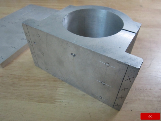
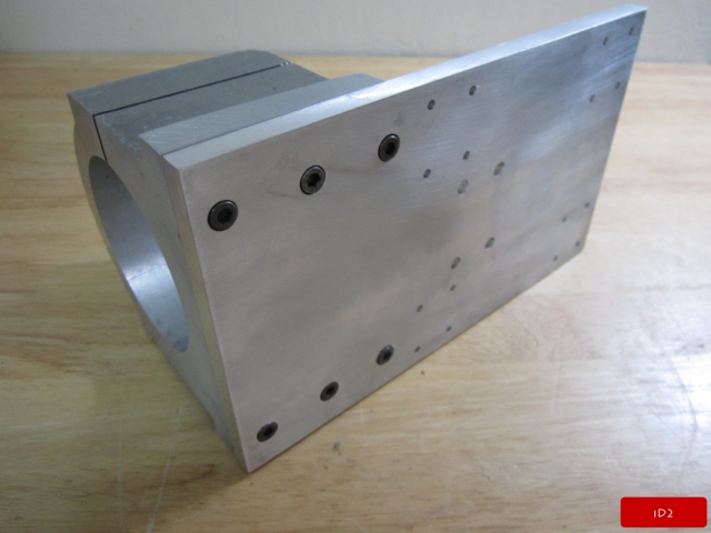
If this spindle clamp size Dia=65mm, length = 120mm it will fit to my z axis plate and for Dia=80mm, length= 130mm it will fit too. But for my spindle clamp it a bit wide than standard spindle clamp it length= 150mm.
-
4th August 2013, 10:17 AM #19
GOLD MEMBER
- Join Date
- Feb 2004
- Location
- Oxley, Brisbane
- Age
- 79
- Posts
- 1,826
I think I understand what you are saying, however, possibly a better way to go would be to have an individual 10mm thick spindle clamp adapter plate that mounts to the Z spindle plate. This would then give you the best of both worlds.
Alternatively, just make the mounting plate 20mm wider and the clamp that you used as an example would then bolt on from the front using holes tapped into the Z spindle plate.
The example you show does not have to clamp from the rear, it just makes it look prettier if it does. There is plenty of room on the flanges to allow for bolts.Bob Willson
The term 'grammar nazi' was invented to make people, who don't know their grammar, feel OK about being uneducated.
-
5th August 2013, 10:57 AM #20
SENIOR MEMBER
- Join Date
- Mar 2007
- Location
- Melbourne - Mexico
- Posts
- 152
You are making great progress ID2.
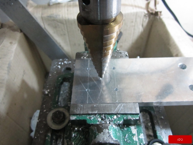
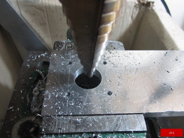
It's a shame you dont have access to a CNC machine to mark out all the bolt holes. Looks very tedious having to mark everything
Keep up the good work and keep posting pictures
What stepper drivers are you using? They look like Crystal System units, which i have in my X4 mill
-
6th August 2013, 03:57 AM #21
Intermediate Member
- Join Date
- Jul 2013
- Location
- Asia
- Posts
- 33
Originally Posted by Bob Willson
 Thank you for your advice.
Thank you Originally Posted by seafurymike
Stepper driver i use M542 (No manufacturer name)
-
27th August 2013, 10:12 PM #22
SENIOR MEMBER
- Join Date
- Nov 2009
- Location
- Melbourne, Victoria
- Age
- 28
- Posts
- 69
I am really liking your build, thank you for posting all the photos. I have a question, what thickness of Aluminium plate are you using?
Regards Ben
-
31st August 2013, 06:17 AM #23
Intermediate Member
- Join Date
- Jul 2013
- Location
- Asia
- Posts
- 33
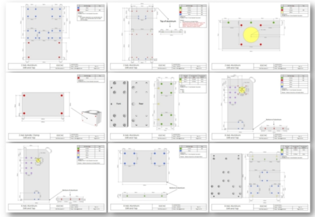
Y Frame , 12mm (5083 or 6061) Originally Posted by benupton
Z Axis & Other , 10mm (5083 or 6061)
-
25th July 2015, 03:37 AM #24
Intermediate Member
- Join Date
- Jul 2013
- Location
- Asia
- Posts
- 33
Hello, After finish my CNC v.2.0 for long time now my new design and improve some issued from v.2.0 , my cnc design v.2.1 will release soon and will finish CNC plans document soon.
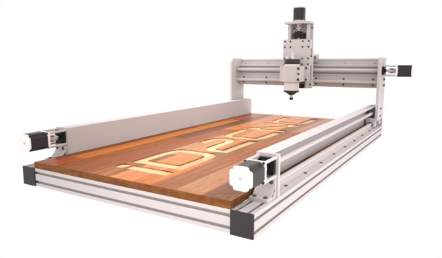


More detail please visit --> iD2CNC.com or iD2CNC.wordpress.com
-
3rd August 2015, 05:29 PM #25
Intermediate Member
- Join Date
- Jul 2013
- Location
- Asia
- Posts
- 33
Now my CNC Plan was finished.
Plans contents ::
B.O.M (Machine 2ft x 4ft).
B.O.M (Machine 4ft x 4ft).
Machine explode views & part detail document (include 2ft x 4ft and 4ft x 4ft).
Reference parts detail document.
Assembly guide document.
Assembly guide video.
Electronic wiring diagram.
Mach3 config guide.
Aluminum 2D (DXF Files).
iD2CNC Machine v.2.1 Specification (2ft x 4ft) ::
Machine working area 650mm x 1250mm
Machine size 1000mm x 1600mm x 700mm (width x length x height).
Design using metric unit (mm).
Dual motor and ball screw on Y Axis.
iD2CNC Machine v.2.1 Specification (4ft x 4ft) ::
Machine working area 1250mm x 1250mm.
Machine size 1600mm x 1600mm x 700mm (width x length x height).
Design using metric unit (mm).
Dual motor and ball screw on Y Axis.
More detail --> http://id2cnc.com/
-
3rd October 2015, 11:58 PM #26
Intermediate Member
- Join Date
- Jul 2013
- Location
- Asia
- Posts
- 33
iD2CNC Plan now it ready --> id2cnc.com

 Reply With Quote


